
This is part two of Working with CAD, which includes: Building a new project using a CAD background
Part one includes: Linking CAD files to Revit
Part three includes: Export to CAD
Building a new project using a CAD background
You can use linked AutoCAD data within a Revit model as an underlay and model building objects such as walls, doors, and windows by either tracing over the lines or by using the Pick Lines option. When linking AutoCAD data in your project, it is important to ensure the CAD file is pinned so it maintains its position.
Exercise files:
Open the TraceImport [2023].rvt exercise file.
Use the ExistingBuilding.dwg exercise file.
Estimated time to complete topic:
15 minutes
Topic steps:
12
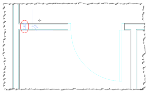
1. If you want to match the thickness of the walls in the AutoCAD file, you can measure them to determine their thickness. Zoom in on a corridor wall to be measured.
2. On the Quick Access Toolbar, toggle on Thin Lines. This displays all lines in the project as a single width. This will help you distinguish the CAD lines more easily.
3. On the Quick Access Toolbar click Measure Between Two References.

4. When you hover the cursor over the walls, the CAD lines highlight. Click on the face of a wall, then click on the other face of the same wall. When you do, the temporary dimension reads 0’- 4 7/8”.
5. Now, place walls over an AutoCAD file. From the Architecture ribbon in the Build panel, click Wall.
6. Next, expand the Type Selector and choose Interior – 4 7/8” Partition (1-hr).
7. In the Properties palette, set the Location Line to Finish Face: Exterior and Top Constraint to Level 2.

8. In the Draw panel, choose Pick Lines. Starting at the upper left, begin placing the corridor walls based on the AutoCAD file interior walls.
9. When you hover the cursor over the finish face of a wall, a dotted line appears. The line is positioned based on the Location Line. In this instance, with Finish Face: Exterior selected, the dotted line indicates the wall centerline based on the wall type you specified.

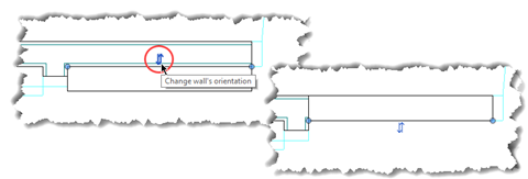
10. Click to place the wall once the dotted line is positioned correctly. If you place a wall in the wrong location, you can use the flip control to correct its placement.
11. You can place one wall on each side of the corridor and use the Trim/Extend to Corner tool to help connect walls. With this tool activated, simply select the two walls you want to extend to form a corner.

12. When you are finished, click Modify to end the command. Take note that you can open TraceImportFinal [2023].rvt to compare the corridor walls with your model.

Ready for more? Head to Working with CAD part three for: Export to CAD
Or go back to the AEC Collection Quick Start Guide for Architects


