This document explores HVAC system design for Autodesk Revit software—including recommended workflows, best practices for HVAC modeling and using the System Browser during design intent modeling. And taking the design intent into Revit fabrication modeling and using fabrication parts for detailing.
Mechanical duct modeling in Revit
While in Autodesk Revit, link the Architect’s model into your project to ensure that your MEP model will remain current.
Place air terminals throughout your project; add elevations and air flows using the Options Bar and Properties Palette. Connect air terminals to mechanical equipment with ducts to create duct networks.
You can choose from predefined duct types or use the Routing Preferences dialog to assign the fittings you wish to use.
Draw ducts directly from the connectors on air terminals and mechanical equipment. Revit will create air systems. MEP connectors are logical entities that enable the calculation of loads in a project.
You can connect ductwork together simply by dragging the duct’s connectors into another segment of ductwork. Snaps and snap lines help to expedite the process. Fittings are automatically placed for you.
If you split a section of ductwork and then change its size, the appropriate transition fittings will be added for you.
You can easily switch to a section view at any time to continue modeling.
Revit provides an intuitive set of tools to help you model intelligent HVAC systems for your MEP projects.
Modeling devices, equipment, and duct networks in Revit
Mechanical system hierarchy in Revit
The powerful modeling capabilities of Autodesk Revit allow parametric system data to propagate throughout your projects.
In the Systems Browser, you will find a list of components for each discipline. When an item is selected from a duct network, you can choose the appropriate system equipment. In the System Browser, a folder is created for the mechanical equipment that contains the air system. Air terminals are listed at the end of the systems hierarchy.
By properly structuring MEP systems for your connected networks, you will be able to take advantage of the data propagation capabilities of Revit. This BIM approach to MEP design will enable you to perform pressure drop calculations and other analyses, helping your project achieve optimal performance.
Leverage Revit’s system browser to facilitate analysis
Generate duct systems in Revit
Autodesk Revit enables you to generate complete duct layouts.
The Conversion Settings dialog allows you to specify desired parameters for elevations, duct sizes, and other ductwork settings.
Select the system components to include in your duct layout. The Duct tool will generate several Solution Types. You can modify these solutions while in the Edit Layout mode to create a custom layout.
Take advantage of Revit’s BIM capabilities for the generation of duct system layouts to help you achieve optimal building system designs more quickly and easily.
Optimize your design with Revit’s duct system layout generation
Mechanical duct sizing in Revit
Autodesk Revit provides sizing methods and constraints for duct sizing.
You can select a dynamic sizing method for the ductwork of a duct system in a project using the Duct Sizing dialog. Developers can also leverage the Revit API to create calculation add-ins to supplement the provided methods.
These features help you tailor Revit’s behavior to match your sizing preferences as design changes occur throughout your projects.
Harness Revit’s powerful automatic calculations for duct sizing
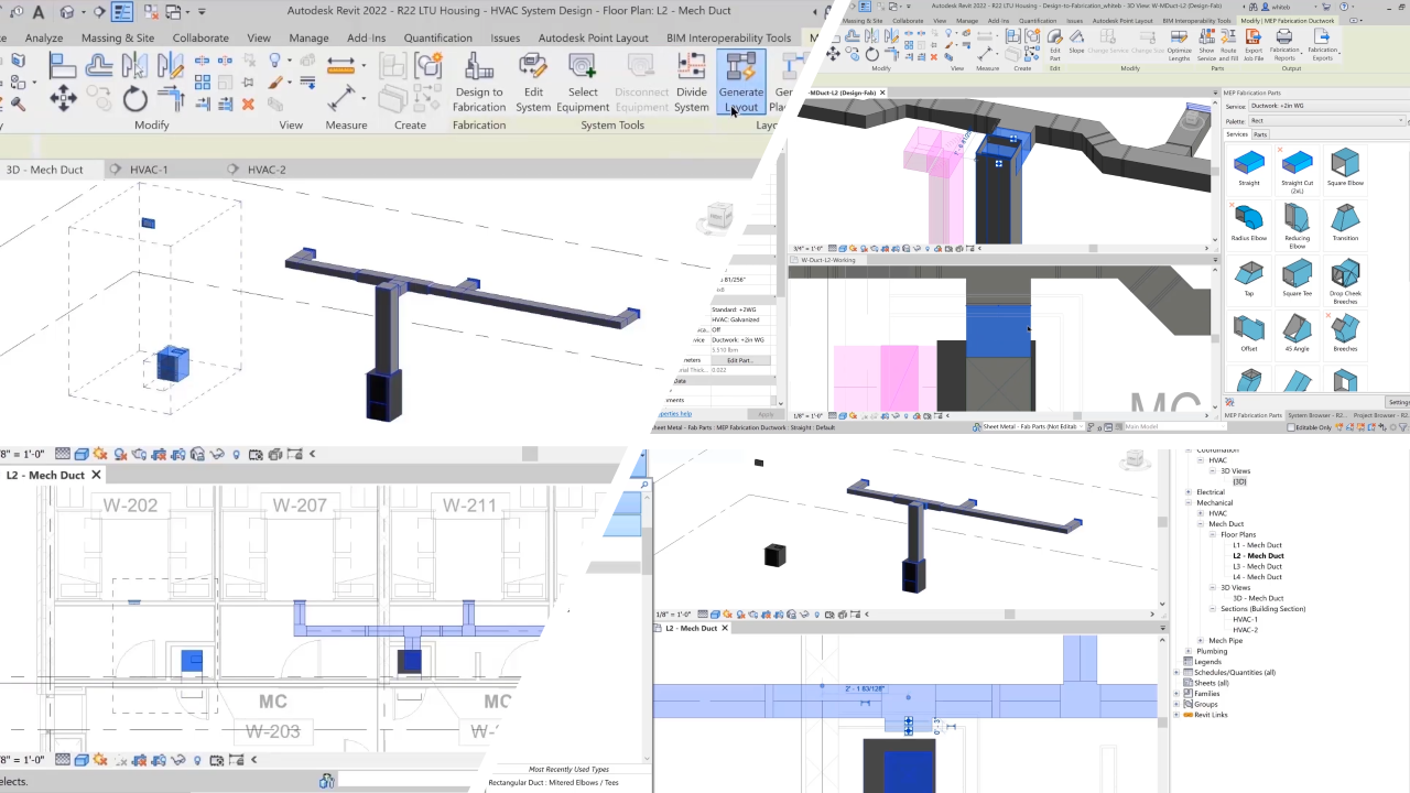
Design intent to fabrication workflow in Revit
A detailer using Revit can easily convert a design intent model provided by the engineering team into a fabrication-ready model—saving time and improving quality.
Select the services you would like to use to include them in your fabrication configurations.
Within the MEP Fabrication Parts palette, select the parts you intend to use during the conversion.
While in exclusion mode, you can deselect any parts you do not wish to use.
Select a design-intent duct network and choose to have Revit automatically convert the design to fabrication expediting the detailing process.
In the drawing area, you can easily delete parts from the design and continue detailing with tools such as Quick Connect, Route and Fill, and Multi-Point Routing.
You can select Fabrication parts directly from the parts browser and place them onto parts in the drawing area.
During the conversion process you can make changes to the design-intent model, such as the shape and size. Or add mappings for in-line parts.
You can use Optimize Lengths to change your flange locations to manufacturable lengths.
The interoperability of the Autodesk Revit Extension for Autodesk Fabrication is used to communicate Revit with the Autodesk Fabrication products.
The Design to Fabrication features in Autodesk Revit help to bridge the gap between design intent and fabrication-ready modeling—connecting MEP systems engineering, design, and detailing workflows across the lifecycle of your projects.
Make a Revit design-intent model a fabrication ready detailed model
To view all workflow tutorials in this series, please visit this post on the Revit Blog. The videos are also available on YouTube as "1-minute snippets" and "3-minute demos". Thank you for taking the time to explore these workflows for buildings enabled by the Autodesk AEC Collection!


