Issue:
How to analyze a lifting frame suspended from cables in Nastran In-CAD or Inventor Nastran.
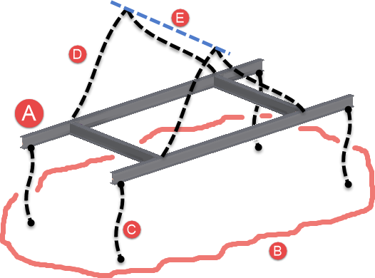

Figure 1: Example lifting frame.
- The top image shows a schematic of the complete project, including (A) the lift frame to be analyzed, (B) the load, (C) the four cables that transfer the force to the frame, (D) the four cables that are used to lift the frame, and (E) the spreader bar used by the crane.
- The bottom image shows what needs to be modeled for the analysis: the lift frame A. Use the type of elements that is appropriate for the simulation: beam, shell, or solid. Beam elements are used in this example with the cross section display activated.
Solution:
Create the CAD Model
Before entering the Nastran environment, add work points or a sketch line that includes the points to which the lifting cables or rigging (D in Figure 1) connects. In Figure 2, a line was created in a sketch to represent the spreader bar. The cables will be connected to points 1 and 2. (If the four lift cables are attached directly to the crane hook, then only one point is needed in Figure 2: a point directly above the center of gravity.)
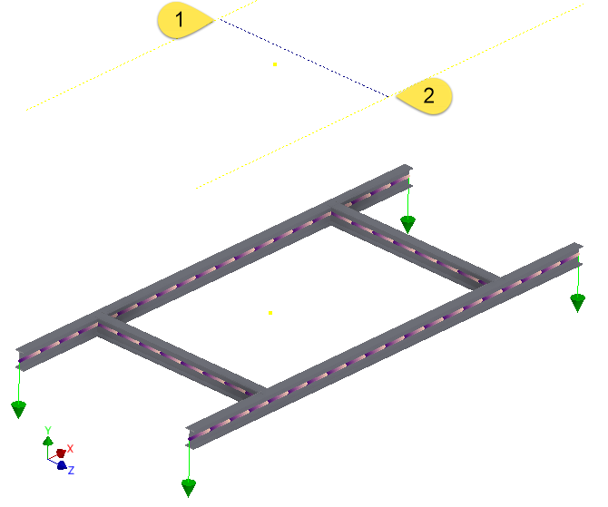
Figure 2: Create geometry to define the suspension point of the rigging.
Create the Cables in Nastran
The lift cables D (Figure 1) are significant in this example because they create forces that put the frame in compression. Constraints on the lift frame A at the location where the cables attach will not produce the same reaction forces.
In the Nastran environment, add a "Connector > Rod" to simulate the lift cables D.
- Select the two endpoints for the first cable (cable 1 in Figure 3).
- Enter the cross-sectional area (A) for the rod.
- Leave the torsional constant (J) and coefficient for stress recovery (C) blank.
- Select the material for the cable.
- Click "Next" to create a new rod.
- Define the endpoints for the next cable (cable 2).
- Repeat steps 5 and 6 for the remaining cables (cables 3 and 4).

Figure 3: Four rod connectors added to simulate the cables.
Add Constraints for Stability
The most common mistake is not adding enough constraints to create a statically stable model. If the center of gravity is not directly underneath the suspension point, the frame will rotate. When performing a small displacement analysis (either linear static or nonlinear static with large displacements set to off), such rotations will lead to an unstable solution or unrealistically large displacements. Fully fixed constraints at the lifting point are not sufficient to prevent the model from rotating. Rod connectors do not have all rotational degree of freedom, so a fully fixed constraint cannot transmit a moment that would prevent the model from rotating.
Therefore, additional constraints are needed to create a statically stable analysis but not restrict the deformation of the frame. This can be accomplished as follows:
- The point or points where cables are suspended (constraints 1 in Figure 4) are constrained in Tx Ty Tz (or fully fixed). Constraint 1 primarily supports the vertical load. (If torsional effects are included in the rod connectors by including the J value, constraints 1 must be fully fixed.)
- Constraints 1 and the rod elements do not prevent the frame from rotating as a rigid body. Constraint 2 is fixed in Tx Tz (horizontal directions) to prevent some of the horizontal motion that would lead to a rigid body rotation. The constraint can be applied to any point on the model, but a point on one of the centerlines of the frame is a good choice. As shown in Figure 4, the point at the bottom of the rod is another choice when the constraint cannot be placed on the centerline.
- Constraints 1 and 2 do not prevent the model from rotating about the line through constraints 1 and 2. Constraint 3, which is any point in the X direction from constraint 2, should be fixed in the Tz direction to prevent all rigid body rotations while allowing the frame to deform in the X direction.
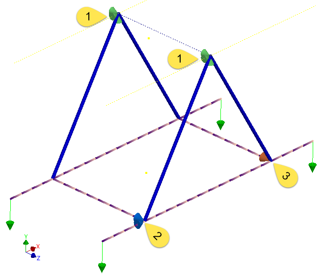
Figure 4: Constraint 1 fixed in Tx Ty Tz. Constraint 2 fixed in Tx Tz. Constraint 3 fixed in Tz.
Check Results and Reaction Forces
In addition to checking the usual results (displacements, stresses, and so on), check the reaction forces in constraints 2 and 3. These constraints exist in the analysis for static stability, so the reaction force should be close to 0. A large reaction force indicates that the frame is not held above the center of gravity, and the constraints are equivalent to attaching a rope to the frame to guide or hold it in place.
Reaction forces can be viewed as follows:
- Right-click on the constraint in the model tree.
- Choose "SPC Summation".
- The dialog shows the components of the reaction force.
Symmetry
If the model is symmetric, consider analyzing 1/4 of the frame. The X symmetry constraint on one symmetry face replaces constraint 2, and the Z symmetry constraint on the other symmetry face replaces constraint 3.
Rod Connection to Solid or Shell Model
The rod element is connected to points or vertices on each end. If the pad eye (or lifting eye) is included in the model of the lifting frame (Figure 5), consider creating a rigid connector inside the hole. This will create the point in the center of the hole to which the rod element is attached. If a rigid connector is not used, the rod element needs to be connected to a vertex on the CAD model, and this will give a high stress "concentration" at that location.
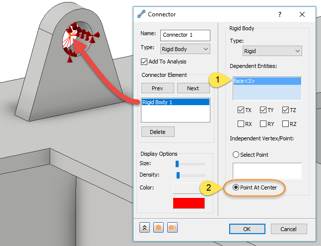
Figure 5: Create a rigid connector in the pad eye if needed using the face of the hole (1) and creating a point at the center (2). The rod connector will be attached to the work point created at the center of the hole.
Products:
Inventor Nastran;