& Construction

Integrated BIM tools, including Revit, AutoCAD, and Civil 3D
& Manufacturing

Professional CAD/CAM tools built on Inventor and AutoCAD

Integrated BIM tools, including Revit, AutoCAD, and Civil 3D

Professional CAD/CAM tools built on Inventor and AutoCAD
Autodesk Support
Apr 22, 2020
This video will orient you to the drafting features unique to the AutoCAD MEP toolset as a way to streamline drawing production, and also set you up to be able to automate calculations. Calculations will be covered in another video.
Video transcript:
Today I will be showing you how to create wiring in AutoCAD MEP. Traditionally, we drew lines between devices to show connections, and there was no intelligence attached to the wires. We had to pick the right layer and type of line we wanted in order to create the wire.
Wires between objects in AutoCAD MEP are actually "intelligent" lines, arcs, and other shapes. We use these to connect devices.

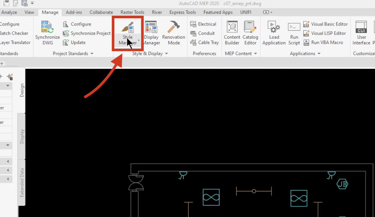
We can go to our style manager and pick wire styles; this will show you the different types of wires are available in your project, and their properties. You can add, delete, or modify any of these to suit your needs. This is how we create intelligence wires in AutoCAD MEP.
There are several ways to access the wire command. One of these is our tool palette. If I wanted to connect these receptacles, I would select 230V Power Wiring and I would pick what Style I wanted. I would select what type of line, an arc, line spine, etc., and I would select an elevation and assign it a system and a panel board, which is LP-1.

I would then hover over an item until I see a green connector. Just select here and make the connection, then hit Enter. And now, I have created a wire between these two devices, and it has intelligence attached to it. It automatically put in the tick marks. I can move those around if I need to clean up the drawing. I can flip them in different directions if I need to.

I can also just click on a device. You will see a small addition sign, and then click on it. Now I can change to arc. You will see the elevation and other properties assigned. Then click to connect the devices. I am just going to connect all these devices, and finally, the junction box. Then what I'll do is hit Enter.
Click in the direction of the panel board, and it automatically creates my home run for me. Now I have intelligent devices or objects between each of the devices here.
If I select this light, I can add a connector here. I can click on it and select 'add', I can pick arc, and I can add an elevation.
This time I want to select my ceiling lights, so I will change that and leave the same circuit. Then, I will select each of the devices, just like I had before, and connect one to the other. You'll notice these are different colors, they are on a different layer than the other wires.
The AutoCAD MEP toolset automatically assigns a layer to each wire based on what system we put them in. This is just an example to show you how easy it is to add wires using the MEP toolset.
Was this information helpful?
The Assistant can help you find answers or contact an agent.
What level of support do you have?
Different subscription plans provide distinct categories of support. Find out the level of support for your plan.
How to buy
Privacy | Do not sell or share my personal information | Cookie preferences | Report noncompliance | Terms of use | Legal | © 2025 Autodesk Inc. All rights reserved