Issue:
When generating a solid mesh (steps 1 and 2 in figure below), the message "Meshing Failed" is given (step 3). This occurs in Nastran In-CAD (version 2019.2 or older) and Inventor Nastran (version 2020.0 and newer).
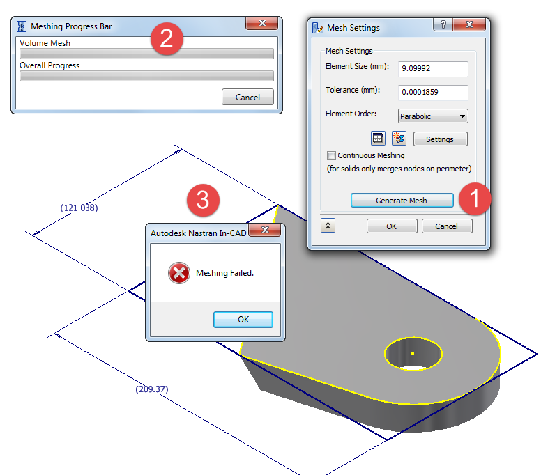 Figure 1: Solid mesh ends in failure.
Causes:
- Adjacent surfaces have slightly different edges (mathematically), so the mesh does not "knit" together to make a solid.
- Too coarse mesh settings on the particular part.
Solution:
Note: The meshing of a solid may fail during the surface mesh or the volume mesh. These steps will help for either situation.
Diagnose the Issue
One way to diagnose the issue is to change the mesh type from Solid to Shell; that is, change the Idealization. When the model is surface meshed, the edges that do not match will be shown by a heavy edge (white in Figure 2). Also, note how the mesh does not match between adjacent surfaces.
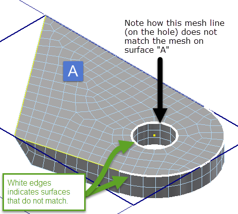 Figure 2: White edges indicate where surfaces do not match.
This mismatched mesh provides a clue to
where the issue occurs. In order to get the mesh to match, the tolerance can be adjusted so that the edges are mathematically identical. Change the idealization back to solid and try a different tolerance. (See Figure 3.) Since this model is 20 x 121 x 209 mm, a tolerance on the order of 0.1 to 1 mm is reasonable. The model meshes with the revised tolerance.
Figure 3: "Mesh > Mesh Settings" and change the mesh tolerance. The tolerance may be on the main mesh dialog (as shown here) or under the "Settings" depending on the version of the software.
Solve the Issue in the CAD Model
Rebuild the Parts
The tolerance may not solve the meshing for all parts when working with an assembly. In such cases, rebuilding the parts that failed the surface meshing may fix the issue. That is, there may be new or edited features in the part that need to be updated.
- In the Inventor modeling environment, Edit (or Open) the part that failed the surface mesh.
- "Manage > Update > Rebuild All" and "Manage > Update > Update > Global Update"
- Save the part file and "Return" to the assembly.
- Repeat the rebuilding of other parts as necessary.
- In the assembly, "Manage > Update > Rebuild All".
- Enter the Nastran environment and mesh the model.
Fix Model Automatically
Inventor has a Repair Bodies command which can automatically correct a number of modeling and tolerance issues.
- In the Inventor modeling environment, Edit (or Open) the part that failed the surface mesh.
- From the 3D Model tab, choose "Surface > Repair Bodies".
- See the help page About the Repair Environment for instructions on using the repair command.
- Save the part.
- Update the assembly.
- Enter the Nastran environment and mesh the model.
Fix Model Manually
If the mesh of the shell idealization still shows unmatched edges, it may be possible to fix the issue surface manually.
For cylindrical surfaces, use a plane to split the faces in half. ("3D Model > Modify > Split" in the modeling environment for the part.) Using smaller faces and providing more edges to guide the mesher can be helpful. If splitting the faces does not help, try the following:
- In the Inventor modeling environment, Edit (or Open) the part that failed the surface mesh.
- From the 3D Model tab, choose "Modify > Delete Face".
- Select one of the faces that is related to the unmatched edge and delete it. Note that this converts the model from a solid body to a surface body.
- Recreate the surface by using the "Surface > Patch" command. This now created two surface bodies.
- Merge the surfaces into a solid body using "Surface > Stitch".
- Save the part.
- Update the assembly.
- Enter the Nastran environment and mesh the model.
Other Options
If the model still has unmatched edges between two surfaces, it may be necessary to change how the part is constructed in order to eliminate the mesh failure. For example,
- Instead of including a hole in a sketch and extruding the sketch, extrude the sketch without the hole. Then use the Hole command.
- If the issue occurs at a fillet or chamfer or similar feature, change the size of the feature.
- If the issue occurs on extruded parts change Extrusion parameters (for instance use other objects/surfaces not distance for extrusion limits).
- If a sliver surface or overlapping region is the issue, adjust the model to eliminate the sliver surface. (Either cut or "shave" away a small area or add material to blend the surfaces better.)
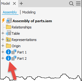
If the CAD model has issues, either the Rebuild will fail or the model tree will show an indication of issues with the part. (See the figure below.) In this case, exporting the model to a STEP file ("File > Export > CAD Format") and opening the STEP file may correct the issue.
Too coarse mesh settings
Try decreasing the mesh element size in the Mesh Settings of the problematic part.
Products:
Inventor Nastran;


